
I have a plasma globe that I received about 15 years ago to create illustrations for an article. One day I showed interesting experiments with it, but now I would like to write about why the globe broke down.
As is well known, the plasma globe (or Tesla globe) is a decorative glass sphere filled with low-pressure noble gas, in which spectacular, colorful plasma tendrils twist and curl in the electric field created by high-frequency high voltage.
The globe operates from a high-voltage power supply similar to a Tesla coil. This power supply is in the base of the globe, depending on the size of the globe. It produces approximately 15–25 kV, at a frequency somewhere between 15–45 kHz. The high voltage is fed to the glass electrode in the center of the globe, which is usually coated on the inside with a thin graphite layer. The wall of the electrode is insulating; current does not enter the globe directly, but via capacitive coupling it excites a high-frequency electric field, which ionizes the gas inside the globe.
Inside the globe there is a mixture of low-pressure air and noble gases, which glows pale pink. (The pressure is about 0.3–1.5% of atmospheric pressure, 3–15 mbar.) The composition of the noble gases determines the color. Neon gives a more intense orange, argon a bluish-purple, helium a yellowish-white, krypton white, xenon bluish-white.
Unfortunately, plasma globes break down by themselves over time, even if they are not used. One can read various opinions about the reasons on several internet forums, which are mostly wrong. I would like to clear the fog, so I will describe how my globe went bad.
The fault
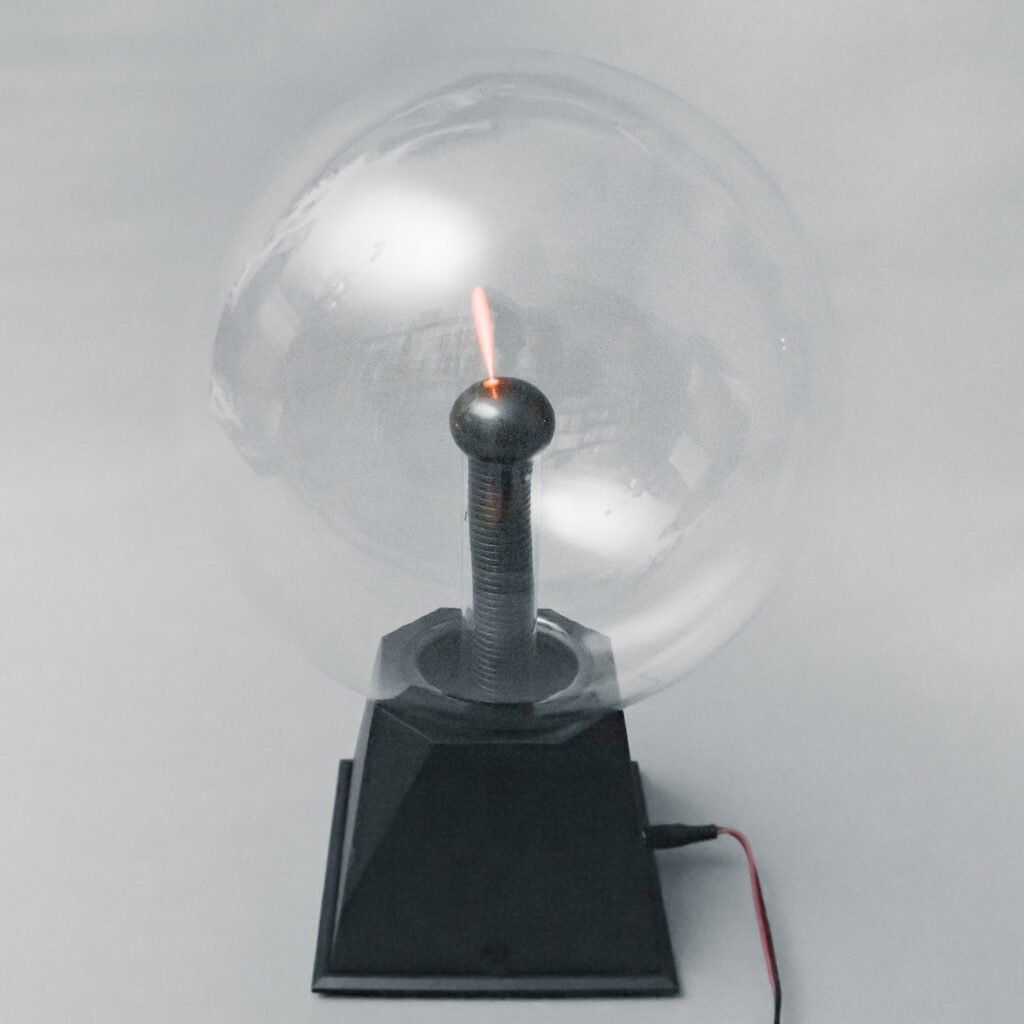
As can be seen in the picture, over time the winding, dancing bright thread-like lightning disappeared, and the globe produced only a small, 3–4 cm “spike”. This could also be a fault of the power supply: if it has weakened and does not provide a high enough voltage, there will be hardly any ionization. But that is not the case here; the power supply works well. The power supply originally ran from 12 V DC. Since there were no critically sensitive components in it, I cautiously tried what happens if I increase the voltage to 15…18 V. The power transistor—driving the high-voltage transformer—of course heated up more, but the transformer coped, it did not get hotter, and it did not break down. By fitting a larger heatsink to the transistor, the device became operable for longer periods from a higher supply voltage.
However, the beautiful, winding, colorful plasma threads still did not appear. The bluish-purple shades disappeared completely; instead, monochrome, orange-pink, completely straight rays jumped around in the globe.
What happened to the globe?
The color change indicates that the composition of the fill gas in the globe has changed. The fact that there was only a short spike, and that threads spanning the whole globe appeared only at higher voltage, shows that the conditions for ionization, and the gas pressure, also changed.
On most internet forums, the phenomenon is explained by failure of the electronics, by the transformer weakening. This explanation cannot be completely excluded either. In that case the explanation would be that raising the supply voltage compensated somewhat for the weakening of the high-voltage transformer. However, this is not the case for us; I measured the power supply and it proved to be good. The fault is in the globe, and reading others’ writings I concluded that this phenomenon is not rare and also occurs with globes that have not been used for a long time.
The spectacular filament range of plasma globes is typically a narrow pressure and gas-composition window: if the pressure is too low, the discharge “thins out”, if it is too high, it starts with difficulty.
According to Paschen’s law, the breakdown voltage (𝑉𝑏) is a nonlinear function of the product of gas pressure (𝑝) and the electrode spacing (𝑑): 𝑉𝑏 = 𝑓(𝑝⋅𝑑). The curve is characteristically U-shaped; it has a minimum where, for a given gas, the discharge starts at the lowest voltage. More: https://en.wikipedia.org/wiki/Paschen%27s_law
That “it starts only with higher supply voltage, and the filaments have shortened and straightened” is because the system has moved away from the optimal range toward either too low or too high pressure. In a peculiar way, higher pressure causes thinner, sharper filaments, lower pressure thicker ones.
On the forums I read, several people wrote that “the globe must have cracked, air got in.” No. If the globe cracks, within a short time it becomes completely air-filled and atmospheric pressure develops inside the globe. Such a globe shows no sign of life. I know this from experience, because my first oscilloscope (which I received from my father at age 12, a dual-beam, 25 MHz EMG-1569) failed like this: during the 1985 earthquake in Hungary it was hit, and the cathode-ray tube cracked 4–5 mm long next to the screen.
But this plasma globe is not cracked; its wall is completely intact, and there is no question that air has gotten into it.
Do you know why an inflated balloon slowly deflates over time? Not because its mouth is tied badly. The gas escapes through the balloon wall. In practice you cannot make gas-tight rubber. No matter how tightly you tie the balloon’s mouth, the gas will escape, and through the entire surface of the balloon. You can also observe that helium-filled balloons deflate sooner than those inflated with air.
Gases can pass through solid materials by permeation (dissolution in the wall + diffusion + desorption). And not only through rubber, but through glass as well, though much more difficultly. Permeation proceeds more easily the smaller the gas particles are. Large molecules, such as hydrocarbons (kerosene, gasoline, organic solvents) diffuse through plastics relatively easily, for example PVC—therefore it is not a smart idea to store gasoline for long periods in a closed room in a PVC can. Smaller, diatomic molecules such as nitrogen (N₂) and oxygen (O₂) in air pass through materials more easily, but their passage through glass is so small that it is very difficult even to measure. Noble gases do not form diatomic molecules; their atoms are solitary, so they are smaller. Permeability depends strongly on which noble gas it is; for example helium is very mobile and passes easily even through borosilicate glasses, neon less so, krypton and xenon even less.
So gases can pass through the glass sphere over time as well. The driving force of diffusion is the external and internal partial pressure difference: J ∝ (Pin − Pout). The flow (J) always occurs from the higher-pressure side to the lower-pressure side. If the pressure inside is lower, it goes inward; if the pressure inside is higher, it goes outward.
Based on this, we might think that since there is only about one percent an atmosphere of pressure in the plasma globe, gases will move inward through the globe wall. But there is a twist here. Diffusion is not determined by the total pressure of all gases, but for each gas separately, by that gas’s partial pressure. Partial pressure is the pressure we could measure if that gas were present alone. The total pressure measurable in a gas mixture is the sum of the partial pressures of the individual gases that make up the mixture. For example, if the globe contains a mixture of one part air and four parts neon, with total pressure Ptotal = 5 mbar, then
Pinner = Pair + PNe = 1.0 mbar + 4.0 mbar = 5.0 mbar.
Let us take air as a mixture of ~80% nitrogen and ~20% oxygen. In this case PN₂ = 0.8 Pair = 0.8 mbar, PO₂ = 0.2 Pair = 0.2 mbar. Thus
Pinner = PN₂ + PO₂ + PNe = 0.8 + 0.2 + 4.0 = 5.0 mbar
Outside the globe there is only air, i.e., there is no neon:
Pouter ≈ PN₂ + PO₂ ≈ 800 mbar + 200 mbar = 1000 mbar.
The partial pressures of nitrogen and oxygen are higher outside than in the globe, therefore these gases will diffuse inward through the glass wall. But what about neon? The partial pressure of neon is 4,0 mbar inside, and 0 mbar outside, because there is no neon outside. Therefore neon will diffuse outward.
Even though the pressure in the globe is only about half of the external atmospheric pressure, the noble gases come out of the globe. This is a very important observation.
What is the net process?
Every component follows its own partial-pressure gradient:
- N₂, O₂: partial pressure is higher outside → inward driving force.
- Ne, Kr, Ar and other fill gases: outside ~0 → outward driving force.
The key is that the permeability of different gases in glass varies widely. It is common that glasses “let through” light noble gases (especially He; also Ne) to a noticeable extent, while O₂/N₂ permeation at room temperature is much smaller.
Since the constituents of air diffuse inward through glass much less than noble gases diffuse outward, it is assumed that the gas in the globe decreases. As a result, the already low internal pressure does not increase (as it does when a glass balloon cracks), but decreases further. This is surprising, isn’t it?
How can we convince ourselves that the theory is correct?
Well, the best would be if we could somehow measure the pressure and composition of the gas in the globe. But it is not enough to measure it now (the pressure change is small); we should also have measured it when the globe was still good. On top of that, since we are talking about gases, temperature is not negligible during measurement. That ship has sailed; we can no longer measure what the pressure was when it was new. And for some reason I doubt that we could obtain reliable data from the Chinese manufacturer, since it is already difficult to determine who made the globe.
However, there are two telling sign that supports the theory. The first is that the filaments have become thicker, which, according to the manufacturer’s specifications, indicates a decrease in pressure. The second is the color of the plasma threads. Originally it had a bluish-purple shade, which suggests that it contained argon. By now this color has disappeared, so argon is missing from the globe. And here we have arrived at the window replacement.
What is the broken plasma globe’s electronics good for?
Well, as I wrote above, this electronics is something like a Tesla coil. The electric field it creates can not only make the gases in the globe glow. If we bring a fluorescent tube close to it, that will also glow without being connected to the electrical grid. And it also makes the argon glow, which is used to fill insulated windows.
Nowadays, due to energy saving, doors and windows made with two- or three-layer glazing are becoming increasingly widespread in our buildings. The heat transfer coefficient of multi-pane window glazing (the so-called U-value) depends greatly on the thickness of the gas layer between the glass panes and on the quality of the gas. If we increase the gap between the panes, i.e., the thickness of the gas layer, the U-value initially improves (decreases), because a thicker gas layer insulates better. After reaching a certain thickness (for air this is about 12 mm), however, the effect of convection (gas flow, vortices) begins to prevail in the heat transfer in the gas, and the insulating ability begins to deteriorate.
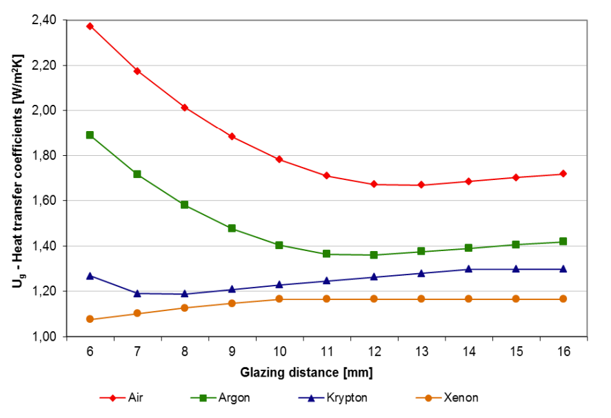
In the attached figure, measured values of the heat transfer coefficient of double glazing can be seen for different gas fills (source: https://acta.uni-obuda.hu/Elek_Kovacs_54.pdf). Two things can be seen in the figure: one is that for different gases, different layer thicknesses are the most favorable. For air 12–13 mm, for argon fill 11–12 mm, for krypton 7–8 mm, for xenon about 6 mm thickness gives the lowest U-value. The other is that noble gas filling improves the U-value noticeably. For example, with the most common argon fill, a U-value below 1.40 W/m²K can be achieved, while if there is air between the panes, it will be around 1.70 W/m²K.
So noble gas filling is a useful thing; because of better insulation it is absolutely worth choosing a window filled with argon gas (provided, of course, that the rest of the house is in order—because if the wind blows snow in through the roof, then argon windows are in vain).
However, there are two problems with this as well. One is that the fill gas disappears over time from between the window panes just as it does from the plasma globe. The main leakage path here is not through the glass but through the polymer edge seal. According to the standard (EN 1279-3, DIN), for a window made accordingly the leakage is <1% per year. This is not much; after 10 years 90% of the gas should still be there. In practice the loss may be larger; in thermal calculations after 10–15 years it is already worth considering whether the gas fill can be taken into account. The loss of gas means the gradual slow deterioration of the window.
The other problem is—this is mainly an Eastern European, even a Hungarian peculiarity—that the window purchased as argon-filled has no argon in it to begin with. Argon is a colorless noble gas; at a glance an argon window looks exactly like one without argon. Thus there are “enterprising” glaziers who undertake installation of argon windows in such a way that there is not even an argon cylinder anywhere near their workshop.
Argon gas is not dangerous, but there are strict safety regulations for handling high-pressure gas cylinders (Gas Cylinder Safety Regulations; in Hungary the 35/2014 (XI. 19.) NGM decree), which makes purchasing, transporting, and storing such cylinders a hassle. Filling a cylinder containing an amount equivalent to 10 m3 of argon costs about 120 euros, and this is enough for roughly 300–500 windows, so its price should not be a problem, but Hungarian entrepreneurs like to save on everything. Last but not least, assembling an argon window requires more attention and expertise. In short: some people prefer not to bother with it. If the customer asks for an argon window, they write “argon” on the invoice, and “their pencil writes more thickly”.
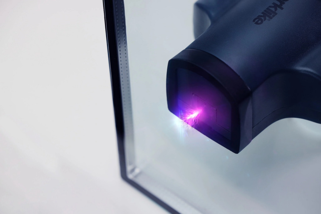
How can we determine whether there is really argon in the window? The standard non-destructive procedure does not use a coil; instead, it creates a plasma in the IGU with a high-voltage discharge and identifies argon from its emission spectrum (Spark Emission Spectroscopy; ASTM E2649). These instruments use an approximately 50 kV spark with a defined electrode arrangement. The power supply of a plasma globe cannot do this. The question is whether anything can be seen at all when we touch its high-voltage output to the window glass. The test performed this way is not definitive, but under amateur conditions it can be carried out cheaply and simply. It is best performed in the dark—or at least when the Sun is not shining—because in bright sunshine it will almost certainly not be visible. This will be a future project.
It is important that for a Low-E coated window this test may not work on the coated side, because the coating can shield the electric field. If there is no shielding metallic coating on the glass, then the bluish-purple light characteristic of argon appears. The Low-E coating is usually on the cavity-facing side of the inner pane (i.e., on the side inside the window) if the window is optimized for thermal insulation (in Hungary this is more common). If the window is optimized for solar protection (which is typical in sunny countries), then the Low-E coating is usually on the inner side of the outer pane. With triple glazing it can occur that two coatings are used: one on the inner surface of the outer pane, one on the outer surface of the inner pane.
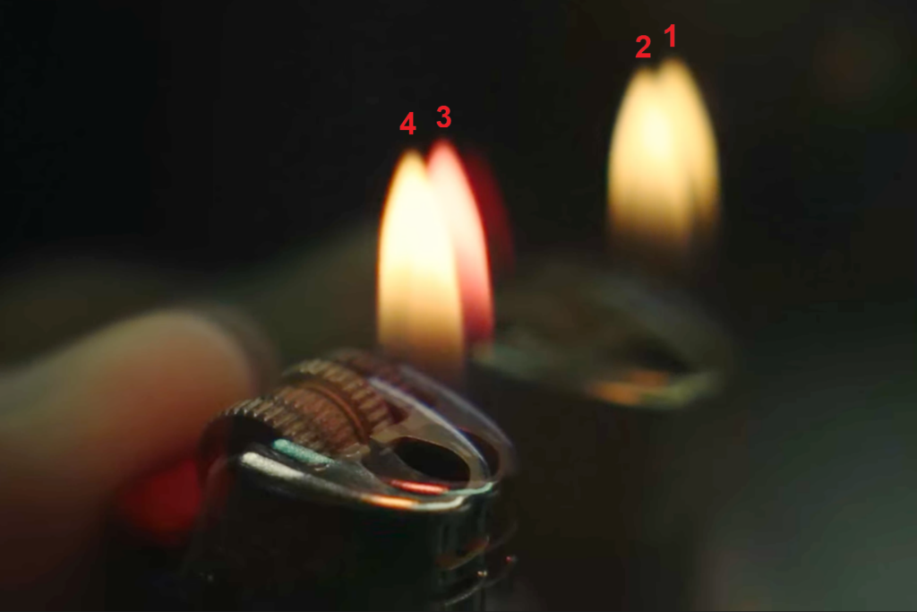
Whether such a coating is present and where it is can be easily determined with the so-called lighter test: if you hold the flame of a lighter in front of the window, you will see reflections of the flame (two per layer, so four for a double-pane unit)—when the color of one flame differs from the others (for example bluish, purplish, or pinkish instead of yellowish), then the Low-E coating is on that surface (for example if the third flame has a different color, then the coating is on the 3rd surface counted from the flame side).