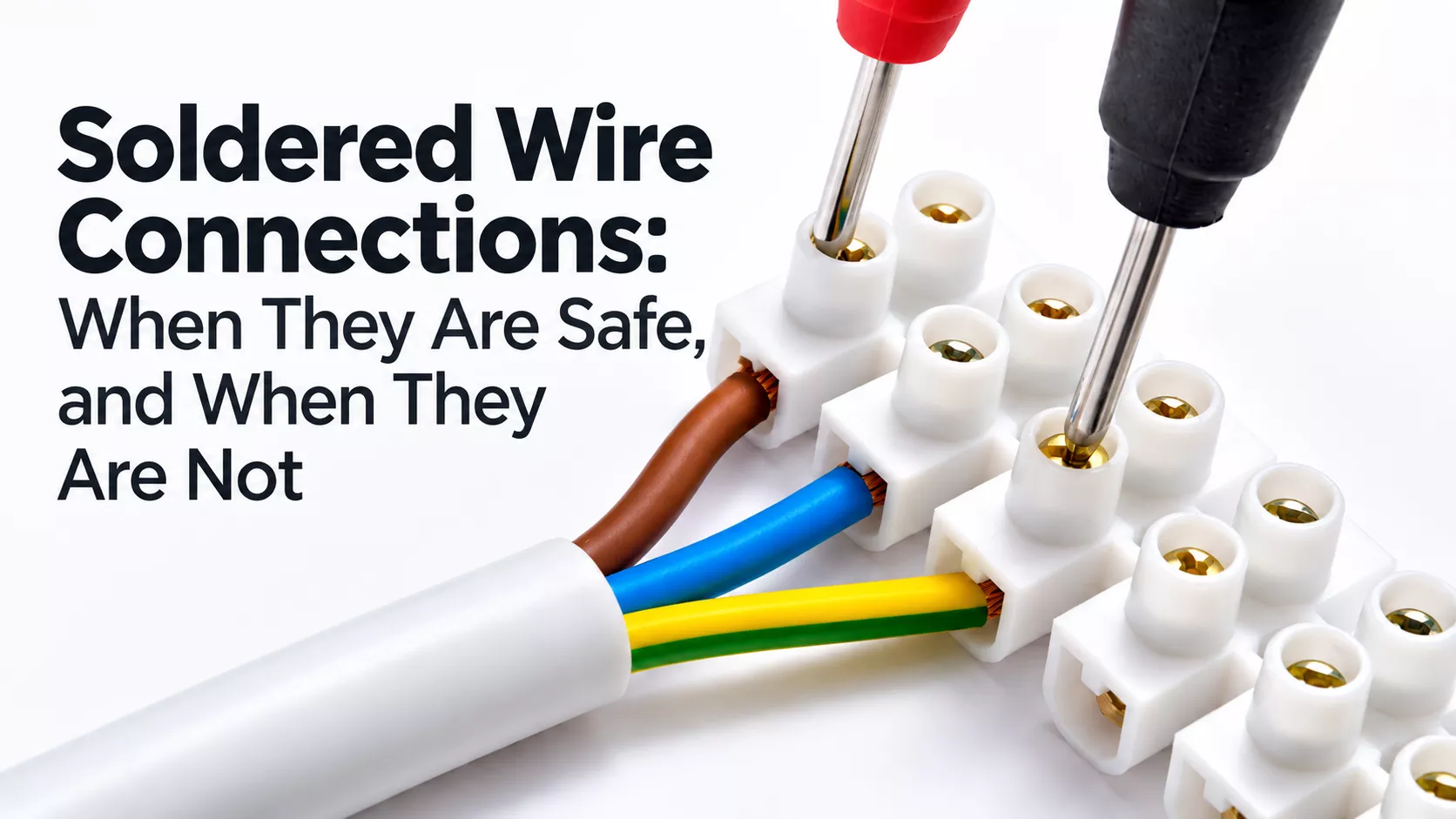
Why a perfectly good solder joint can be a poor electrical connection – and what to use instead in household wiring, appliances and DIY projects.
A twisted pair of copper wires, carefully soldered and wrapped in insulating tape, can stay electrically sound for decades. Open an old European junction box and you may well find exactly that: bright copper, intact solder, and a joint that still measures as well as it did in 1975. Should we keep making household connections this way?
Not by default. Solder is not inherently unreliable, and it does not become dangerous above some magic current. Solder joints carry hundreds of amperes inside industrial equipment every day. Yet a solder-coated wire pushed into an ordinary screw terminal can produce a connection that loosens itself over months, even when it started out excellent.
The useful question is not whether soldering is good or bad. It is where the solder sits, what mechanical load acts on it, and what happens to the connection when something goes wrong. Soldering two conductors together, tinning the end of a flexible wire, clamping a tinned wire under a screw, and soldering a component to a printed circuit board are four different engineering situations. Treating them as one produces some remarkably durable myths.
European installation standards reflect these differences. They discourage soldered connections in power wiring, prohibit soldered joints in protective conductors outright, and restrict solder-tinned flexible conductors. They do not declare every solder joint in every electrical device illegal.
What the European standards actually say
The international reference for building wiring is the IEC 60364 series, adopted in Europe through the CENELEC HD 60364 harmonisation documents and then through national standards. Germany publishes it as DIN VDE 0100 (the current wiring-systems part is DIN VDE 0100-520:2023-06, based on HD 60364-5-52:2011 + A12:2022); Hungary as MSZ HD 60364; the UK as BS 7671. The core requirements are harmonised, but national editions can and do add or tighten conditions.
Four provisions matter here.
- IEC 60364-5-52, Clause 526.2 – Electrical connections. The connection method must be chosen with regard to conductor material and insulation, the number and shape of the wires forming the conductor, the cross-sectional area and the number of conductors joined. A note recommends avoiding soldered connections except in communication circuits; where they are used, their design must allow for creep, mechanical stress and temperature rise under fault conditions. This is a recommendation against routine use, not a blanket ban. (IEC 60364-5-52)
- IEC 60364-5-52, Clause 526.8 – Multi-wire, fine-wire and very-fine-wire conductors. Strand ends must be kept from splaying, either by suitable terminals or by suitable end treatment. Tinned fine-wire and very-fine-wire conductor ends are not permitted at connection points where the soldered and unsoldered portions move relative to each other in service. National editions are stricter in places: BS 7671 (Regulation 526.9.2) states plainly that tinning the whole end of a multi-wire, fine-wire or very-fine-wire conductor is not permitted when screw terminals are used. (IEC 60364-5-52)
- IEC 60364-5-54, Clause 543.3.1 – Protective conductors. Every connection between protective conductors, or between a protective conductor and other equipment, must provide durable electrical continuity and adequate mechanical strength. The clause then states: “Joints shall not be made by soldering.” This is a direct prohibition, not a recommendation. (IEC 60364-5-54)
- IEC/EN 60999-1, Clause 7.1, and IEC/EN 60335-1, Clause 23.9 – Clamping units and appliances. The clamping-unit standard notes that screw-type clamping units are unsuitable for flexible conductors with soldered ends. The household-appliance standard forbids consolidating stranded conductors with lead-tin solder where they are under contact pressure, unless the clamp is designed so that cold flow of the solder cannot cause a bad contact; spring terminals are given as an example. WAGO summarises the practical outcome: both passages restrict screw-type clamps, not screwless ones. (WAGO FAQ)
The sections below translate these requirements into situations found in ordinary homes and workshops.
Why solder and screw terminals make a poor combination
Take a flexible copper wire and the familiar plastic screw-terminal strip, known in British English as a chocolate block.
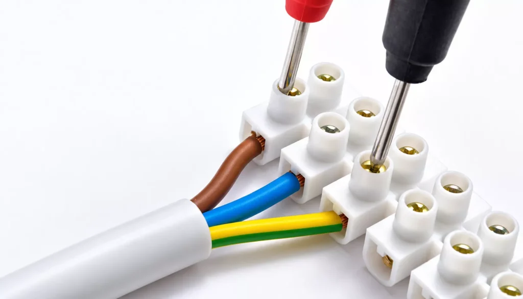
The classic DIY routine: strip the insulation, twist the strands, flood the end with solder, clamp the now-solid-looking tip under the screw. It looks tidy. No stray strands, easy insertion. The trouble is that it puts a soft, creep-prone alloy into a joint whose only job is to keep contact pressure constant.
The problem is creep, not simply melting
Tin-based solders are far softer than copper, and at room temperature they already sit high on their own temperature scale. Eutectic Sn63/Pb37 melts at 183 °C (456 K). A room at 20 °C (293 K) is therefore about 0.64 of its absolute melting temperature. Metals creep noticeably above roughly 0.4–0.5 of that value. Copper, by comparison, is at about 0.22 in the same room.
In practice: when a screw presses on a solder-tinned conductor, the solder slowly flows away from the contact point. This is creep, often loosely called cold flow. The geometry changes, the screw’s preload relaxes, and the clamping force falls, all without the solder coming anywhere near its melting point. Lower contact force means higher contact resistance, especially once oxide films or contamination form.
Higher resistance means more heat. Heating and cooling cycles then accelerate the deterioration. The arithmetic is simple:
A sound screw connection typically sits well below one milliohm. Suppose a degraded one has reached 0.05 Ω. At 16 A:
Nearly 13 W concentrated in a terminal the size of a sugar cube, inside a closed junction box. The conductor may be correctly sized. The circuit breaker may be correctly rated. Neither will notice. A 16 A breaker sees a 16 A load current, not a hot terminal.
Correct and incorrect arrangements
Incorrect: A solder-tinned flexible conductor beneath an ordinary screw.
The screw bears on solder rather than on copper strands or a crimped sleeve, and the solder creeps away from under it.
Correct: A properly crimped bootlace ferrule, where approved for that terminal.
The crimped sleeve holds the strands together and presents a mechanically stable, gas-tight surface to the screw. Alternatively, use the untreated flexible wire if the terminal is rated for it.
Use a ferrule of the right cross-section and length, crimped with a matching tool. Squashing it with ordinary pliers is not the same operation.
Nor should ferrules be fitted indiscriminately. Some spring terminals are designed for untreated flexible conductors, and manufacturers may restrict or condition ferrule use. Phoenix Contact’s technical guidance on EN 60999-1 makes the point that flexible copper conductors do not inherently need ferrules; the terminal design decides whether a prepared or unprepared conductor is correct.
Twisted and soldered joints inside junction boxes
Before compact spring connectors were common, electricians joined solid copper conductors by twisting the stripped ends tightly, soldering the bundle and insulating it. Some of these joints have survived fifty years. Metallurgically, that is no surprise. A clean solder joint between mechanically secured solid copper wires has low resistance and resists oxidation, and in a dry, undisturbed box it sees almost no mechanical load. Longevity, however, is not proof that the method suits a new installation.
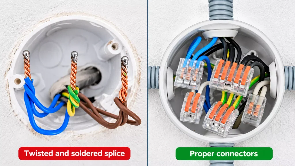
An existing soldered joint should not be judged by age or appearance alone. Its condition, its role in the circuit, the applicable rules and any sign of overheating all count. An electrician inspecting old wiring should assess it, not assume that fifty good years guarantee fifty more.
The practical difficulties:
- Quality depends almost entirely on the individual installer.
- Too little heat gives incomplete wetting; too much damages the insulation.
- Solder wicks along the conductors, creating rigid sections and stress concentrations at their ends.
- Residues of aggressive flux promote corrosion.
- The finished joint still needs insulation, mechanical protection, an enclosure and, where required, access for inspection.
- A strong-looking twist is not a tested connection method.
A proper mechanical splice is also different from twisting two wire ends together by hand. The hand twist gives neither controlled nor repeatable contact pressure.
What should be used instead?
For fixed household wiring, the established approach is a purpose-made connector rated for the conductor material, construction, size, voltage and current. Such a connector has a defined contact geometry and clamping mechanism, and its performance is verified against a product standard (for example the EN 60998 series) rather than depending on the installer reproducing the same solder joint every time. Every such connection must be enclosed and protected as the installation rules require (IEC 60364-5-52, Clauses 526.3–526.7).
Spring connectors: small contact area, large clamping force
Spring connectors are often criticised because their visible contact area is tiny compared with a long twisted-and-soldered splice. Visible area is the wrong quantity. Current actually flows through microscopic contact spots where the surfaces are pressed together, and their total area depends mainly on contact force and material hardness, not on how big the metal parts look.
A spring terminal is designed to keep that force roughly constant through thermal cycling and small dimensional changes; the spring follows the conductor if it settles. Judge a rated, correctly installed spring connector by its tested specification, not by the size of its contact.
Push-in and lever-operated connectors are not interchangeable
Two common types:
- Push-in connectors. Many compact installation connectors of this type (WAGO 2273, for instance) accept solid conductors only. Whether a given model takes stranded or flexible wire is stated in its datasheet, not implied by the family.
- Lever-operated connectors. Suitable versions accept solid, stranded and fine-stranded copper. The lever opens the clamp, the stripped wire goes in, the lever closes the spring onto it.
WAGO’s 221 family, for example, covers several cross-section ranges; the permitted conductors depend on the exact model. The rules are simple: strip to the length printed on the connector, insert each conductor fully into its own entry, close the lever and tug-test.
Do not push two wires into an entry meant for one. Do not assume a connector rated for solid wire takes flexible cable. And do not treat a no-name imitation as equivalent to a tested product.
What about solder-tinned wires and ferrules?
Connector ratings for spring connectors refer to untreated copper, inserted directly after stripping.
Ferrules may be acceptable, but that does not follow from the connector’s cross-section range. WAGO states explicitly that blanket approval for ferrules is not possible: the ferrule must be a tin-plated copper sleeve to DIN 46228-1 or -4, its length must match the strip length, the maximum usable cross-section drops, and the crimp face should sit parallel to the contact.
Solder-tinned ends are a different case from screw terminals. WAGO considers tinning a good pre-treatment for its screwless clamps in stationary installations, because the spring compensates for any settling of the solder. The same manufacturer rules out fully tinned conductors in equipment subject to vibration. So the rule is: follow the connector manufacturer’s statement for that exact product.
Connecting a ceiling light
A ceiling luminaire is the textbook meeting point of fixed wiring and equipment wiring. The building usually has solid copper conductors. The light fitting has short, fine-stranded flexible leads. The two must be joined in a connector approved for both.
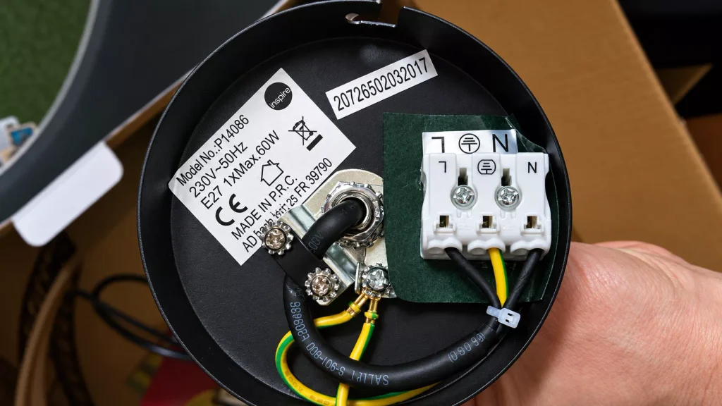
Common mistake number one: tinning the flexible leads so they go into an ordinary screw terminal more easily. Number two: pushing untreated flexible strands into a terminal rated only for solid wire. Choosing the right connector at the start avoids both.
| Connection method | Assessment |
|---|---|
| Flexible lead with a solder-tinned end in an ordinary screw terminal | Avoid; unsuitable for a conventional screw clamp. |
| Flexible lead with a correctly crimped ferrule | Suitable where the terminal accepts ferrules. |
| Untreated flexible lead in a terminal rated for flexible conductors | Suitable when installed to the manufacturer’s instructions. |
| Solid house wire and flexible luminaire lead in a suitable multi-conductor lever connector | Normal solution when the connector is approved for both conductor types. |
| Wires twisted, soldered and wrapped in loose tape | Not a suitable routine method for a new fixed-wiring connection. |
One more detail when replacing an old chandelier: some fittings come with factory-tinned stranded leads. That does not mean every screw terminal can take them. Check the fitting manufacturer’s intended connection method against the terminal specification.
A Class I metal luminaire must also have its protective conductor connected through a proper PE terminal or connector. The earth path must never depend on a soldered splice.
Protective earth: the connection that must survive a fault
In normal operation a protective conductor carries little or no current. Its job starts when a live conductor touches an exposed metal part. That is exactly why its mechanical integrity matters.
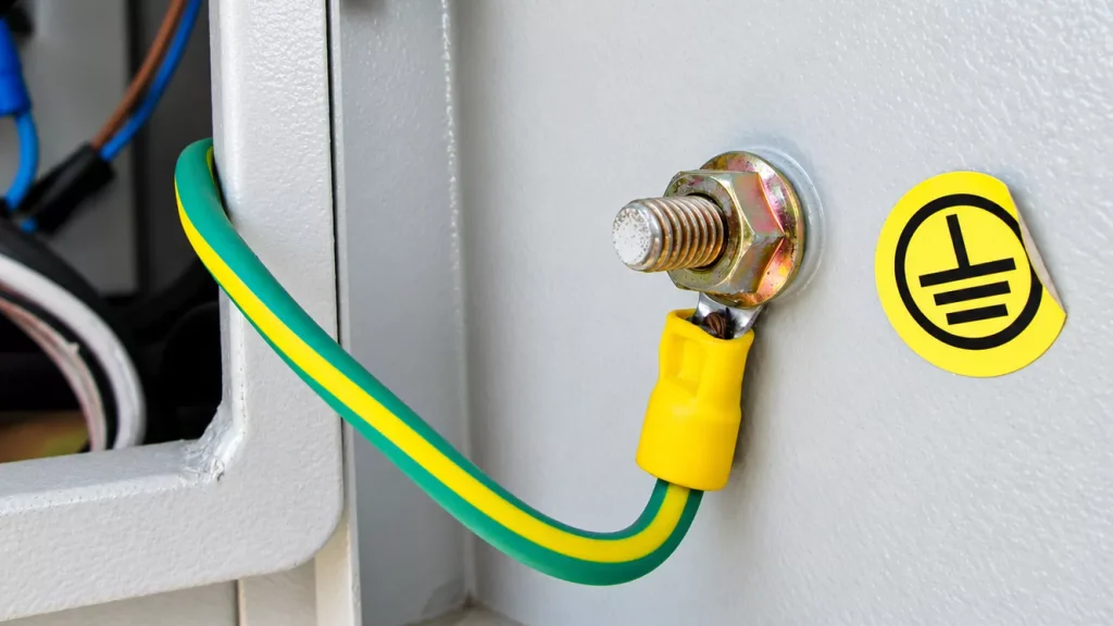
Picture a chafed washing-machine cable putting line voltage on the metal chassis. In a correctly designed installation the protective conductor carries the fault current that makes the circuit breaker or RCD disconnect. In a TN system this can be hundreds of amperes for a few tens of milliseconds, together with the heating and electrodynamic forces that come with it. None of this resembles normal operation.
If the protective connection fails at that moment, the chassis stays live.
Hence IEC 60364-5-54, Clause 543.3.1: protective conductors must be protected against mechanical damage, chemical or electrochemical deterioration and electrodynamic and thermodynamic forces, and their joints must not be soldered.
Practical implications
- Connect the green-and-yellow conductor with a suitable terminal, connector or approved joining method.
- On a metal appliance enclosure, use the designated protective-earth terminal. Never a blob of solder on the chassis.
- A soldered ground connection on a PCB inside a manufactured product is not the same thing as a field-made protective-conductor joint in an installation. Products are designed and assessed under their own equipment standards.
- Functional earth and protective earth are also different things. A ground used for signal reference or EMC is not automatically a safety connection.
- Finally, the protective conductor should not be routed so that removing one piece of equipment breaks the protective path to others.
Crimping: the mechanical alternative to soldering
Crimping is the standard termination method in industrial control panels, household appliances, vehicles and aircraft. A properly engineered crimp forms its electrical and mechanical connection by controlled plastic deformation of both sleeve and conductor. The tool compresses the barrel until the strands and the sleeve form a nearly void-free, gas-tight mass, leaving little room for oxidation to start.
Three things must match: the terminal, the wire and the tool (with the correct die). A bad crimp is every bit as dangerous as a bad solder joint.
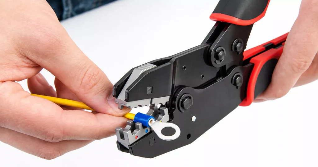
Three common crimped connections
- Bootlace ferrules. Prepare fine-stranded conductor ends for compatible terminals by containing the strands during clamping.
- Butt splices. Join two cable ends, mainly in appliance and low-voltage repairs where such joints are permitted. Insulated, uninsulated and adhesive-lined heat-shrink versions exist; the last type adds moisture protection.
- Ring and fork terminals. Connect to studs or screw terminals. A ring terminal cannot slip off even if the screw loosens slightly, which makes it the choice where accidental disengagement must be ruled out.
Common errors
- A ferrule that is too large cannot be crimped reliably onto a smaller conductor by squeezing harder. The same applies to a terminal crimped with the wrong die.
- Another frequent mistake: soldering the wire into a crimp terminal before or after crimping, on the theory that two methods must be stronger than one. They are not. Solder wicks along the strands, stiffens the transition, and creeps inside the barrel, which works against the crimp’s residual stress. Unless the terminal manufacturer specifies a combined solder-and-crimp process, crimp only.
- Bootlace ferrules are specified in DIN 46228-1 (without collar) and DIN 46228-4 (with plastic collar). WAGO’s guidance adds the practical checks: ferrule length matched to strip length, correct cross-section and a gas-tight crimp.
Can copper and aluminium wires be connected together?
Older buildings in Central and Eastern Europe, Hungary included, often contain aluminium wiring. Joining it to copper needs more care than a copper-to-copper joint.
Aluminium forms a hard, insulating oxide film within seconds of stripping, creeps more than copper under pressure, and corrodes galvanically where it meets copper in the presence of moisture.
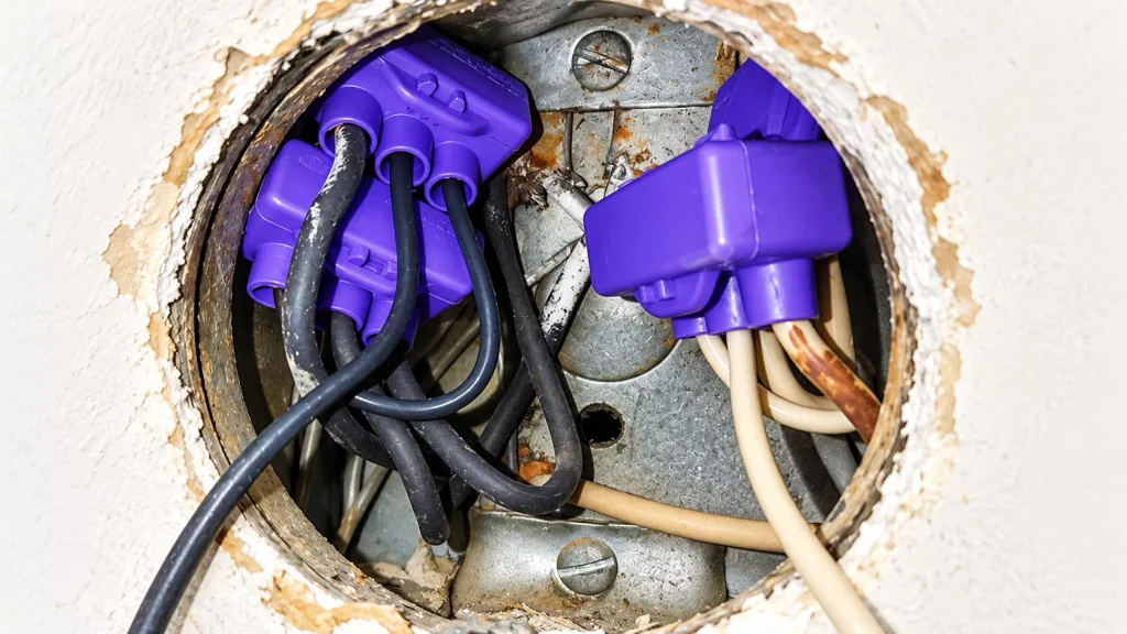
Twisting copper around aluminium and soldering the bundle is not an acceptable general-purpose solution.
Neither is using a copper-only connector because the aluminium wire happens to fit.
The correct method is a connector explicitly approved for aluminium and, where needed, for aluminium-to-copper transitions, installed with the preparation and contact compound the manufacturer specifies.
A common misunderstanding concerns contact paste. Adding paste does not make an unsuitable connector suitable. WAGO, for example, approves its Alu-Plus contact paste only with CAGE CLAMP and PUSH WIRE spring technology up to 4 mm², and recommends its 2273, 773 and 222 series for solid aluminium conductors. The same source states that the 221 series is not suitable for aluminium-to-copper connections because its spring technology is different.
When modernising an old installation, connector selection starts with the conductor material, not with whatever is in the toolbox.
Where soldering is still a perfectly reasonable choice
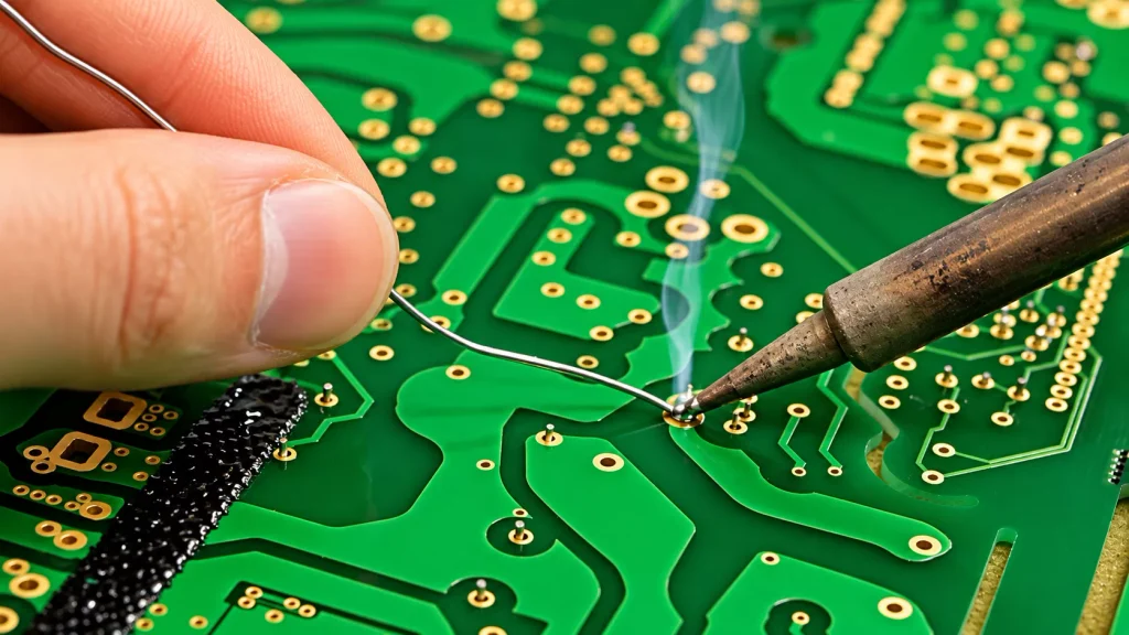
Soldering has taken a beating so far. Yet it remains the standard joining technique in electronics, including equipment running straight off the mains. The application is what differs. A component soldered to a PCB is not under the concentrated pressure of a screw. Its joints are designed as part of the assembly, while component mounting, cable restraints and the enclosure take the mechanical loads. A 230 V power supply can therefore contain hundreds of legitimate solder joints without contradicting any rule for building wiring. The same goes for soldered connections inside transformers, motors and other manufactured equipment. Those products fall under their own equipment standards.
Low-voltage DIY projects
Soldering is often the right choice for permanent connections in small electronics: Arduino builds, LED strips, radio gear, sensor modules.
It still needs thought. Take two flexible wires soldered end to end to repair a cable. Electrically, the joint may be perfect. But solder wicks along the strands well past the joint. That section now behaves like a short rigid rod attached to a flexible cable. Flex the cable repeatedly and the bending concentrates exactly where the solder ends. Sooner or later, strands break at that transition. Heat-shrink tubing adds insulation and a little support. On its own it does not turn a poorly supported solder joint into a reliable cable termination. Dual-wall or adhesive-lined sleeving, extending well beyond the soldered zone, helps considerably.
For a stationary low-voltage circuit, a soldered splice with proper insulation and strain relief is entirely appropriate. For a cable that moves often, a crimp splice or a purpose-designed connector is generally the better choice.
How to make a sound solder joint
When soldering is the right technique:
- Clean the conductors and use an electronics-grade flux (rosin or no-clean). Never use acidic plumbing flux.
- Secure the parts mechanically so the joint does not rely on solder for strength.
- Heat the work, not the solder, until the solder wets the metal surfaces instead of sitting on them as a blob.
- Use enough solder to complete the joint, and no more.
- Keep the joint still until it has solidified.
- Inspect for incomplete wetting, unintended bridges and scorched insulation.
- Insulate the joint and provide strain relief.
A shiny surface alone proves little. Lead-free joints normally look duller and grainier than tin-lead joints of the same quality.
With mains appliances, keep DIY soldering apart from safety-critical repairs. Reassembling an appliance with an improvised internal cable joint can change its original electrical safety characteristics.
Does lead-free solder solve the problem?
The EU RoHS Directive restricts lead and several other hazardous substances in electrical and electronic equipment, with listed exemptions. Modern electronics manufacturing therefore relies on lead-free alloys.
Common tin-silver-copper (SAC) alloys melt at roughly 217–220 °C, against 183 °C for eutectic Sn63/Pb37. The higher melting point does not make a tinned wire suitable for a screw terminal. A SAC alloy at 20 °C sits at about 0.60 of its absolute melting temperature, versus 0.64 for tin-lead. Both are deep in the creep range. Swapping the alloy changes the rate, not the mechanism, so contact pressure, creep and thermal cycling still have to be assessed.
RoHS is also a materials-restriction law, not an installation standard. It says nothing about how household conductors must be joined. The European Commission maintains information on its scope and exemptions.
The other connection mistakes worth avoiding
Solder gets the attention, but several duller mistakes cause just as many hot terminals.
- Two wires beneath one screw: Unless the terminal’s documentation states that it accepts two conductors, clamping two under one screw produces uneven pressure. One wire ends up tight, the other loose. Wires of different diameters make this almost certain.
- Too much or too little stripped insulation: Stripped too far, bare copper sticks out of the terminal. Stripped too short, the clamp bites on insulation instead of copper. Use the strip length printed on the connector or given in its datasheet.
- A damaged conductor: Stripping fine-stranded cable with a knife often cuts several strands. The effective cross-section drops, and the remaining strands may be nicked. Use an adjusted wire stripper.
- Ordinary pliers instead of crimping tools: A ferrule flattened with pliers can look compressed and still have poor contact. Tool and terminal must be mechanically compatible.
- Missing strain relief: A terminal is not designed to carry the weight of a cable or survive repeated pulling. Anchor the cable sheath so that mechanical forces do not reach the electrical connection.
- Connections outside an enclosure: An insulated terminal block is not a complete enclosure. Fixed-wiring connections belong in suitable boxes, accessory enclosures or equipment compartments that provide the required mechanical and environmental protection.
- Ignoring temperature ratings: Connectors and terminal blocks have specified operating temperatures. A connector fine in a room-temperature junction box may fail beside a heating element, inside a hot appliance or in a luminaire compartment. A higher current rating does not compensate for a lower temperature rating. These points are covered by the general connection, protection and enclosure requirements of IEC 60364-5-52 and by the relevant connector product standards.
A practical connection guide
The table covers typical household and workshop applications. Copper conductors are assumed unless stated otherwise.
| Application | Preferred connection method | Avoid |
|---|---|---|
| Solid copper wires in a household junction box | Approved installation connector | Improvised twisted and taped joints |
| Flexible wire in a screw terminal | Crimped ferrule or untreated wire, as the terminal manufacturer specifies | Solder-tinned ends in ordinary screw clamps |
| Solid house wire to flexible luminaire lead | Connector approved for both conductor types | Forcing flexible strands into a solid-wire-only terminal |
| Protective-earth connection | PE terminal, clamp or approved mechanical joining method | Soldered PE joints |
| Flexible wire in a lever connector | Properly stripped, untreated conductor unless another preparation is approved | Unapproved ferrules or tinned ends where the manufacturer excludes them |
| PCB component or wire connection | Proper solder joint with mechanical support | Unsupported cable loads on solder pads |
| Stationary 12 V electronics project | Proper soldering or suitable connector | Bare twisted wires, inadequate insulation |
| Frequently flexed low-voltage cable | Crimp splice or purpose-designed connector | An unsupported, rigid soldered splice |
| Copper-to-aluminium transition | Connector explicitly approved for both materials and the application | Direct twisting, improvised soldering, copper-only connectors |
| Appliance connection near a heat source | Manufacturer-specified high-temperature terminal | General-purpose connectors used outside their temperature rating |
These are selection principles, not substitutes for connector documentation or national rules. Work on fixed mains wiring should be done and verified by a qualified person in line with local regulations.
Five claims about soldered joints that deserve a closer look
The same arguments come up whenever electricians discuss traditional soldered wiring. Most contain some truth. The conclusions drawn from them often do not follow.
“If the solder melts, there is already a much bigger problem.”
Quite possibly. But creep needs no melting, and a termination must stay safe under its specified operating and fault conditions. A correctly rated breaker cannot detect a deteriorating contact or prevent local overheating.
“A twisted connection is already mechanically strong. Solder only improves it.”
A careful twist can be very strong. That still does not make an improvised joint compliant, and adding solder does not turn a non-compliant connection into an acceptable one.
“Spring connectors are unreliable because their contact surfaces are tiny.”
Contact performance depends on force, material, geometry and tested limits, not visible area. A correctly selected, rated spring connector and a wrongly selected one are two very different things.
“There are soldered connections inside powerful inverters, so soldered household wiring must be fine.”
The comparison ignores the difference between engineered equipment assemblies and field-made installation joints. They face different mechanical loads, production controls and standards.
“My soldered connections have worked for forty years.”
Probably true. Forty good years are evidence about those particular joints under those particular conditions. They say nothing about the method’s suitability for every new installation, conductor type or environment.
The same logic cuts the other way: one melted spring connector does not condemn the whole technology. Usually it points to a wrong model, a wrong strip length or an overloaded circuit.
When you open an old box and find a neat soldered splice with no discoloration, the sensible response is usually to leave it, note it and check it with a thermal camera under load. When you are making a new connection, reach for a rated connector.
Technical references and further reading
IEC documents set the international technical framework; European harmonisation documents and national standards determine how they apply in each country.
- IEC 60364-5-52:2009+AMD1:2024 CSV – Low-voltage electrical installations – Part 5-52: Wiring systems. Particularly Clause 526, Electrical connections. IEC publication record
- HD 60364-5-52:2011 + A12:2022 – European harmonisation document; German implementation DIN VDE 0100-520:2023-06. UK implementation: BS 7671, Regulation 526.9.
- IEC 60364-5-54:2011+AMD1:2021 CSV – Earthing arrangements and protective conductors. Particularly Clause 543.3.1. IEC consolidated edition
- IEC 60999-1:1999 – Connecting devices – Safety requirements for screw-type and screwless-type clamping units. Particularly Clause 7.1. IEC publication record
- IEC 60335-1 – Household and similar electrical appliances – Safety – General requirements. Particularly Clause 23.9 (stranded conductors consolidated with solder under contact pressure).
- Phoenix Contact – What is required by standards? Technical guidance on EN 60999-1 and conductor preparation. assets.phoenixcontact.com
- WAGO – Using Ferrules. Permitted ferrule types, dimensions and crimping requirements. Technical guide
- WAGO – Interconnection Technology FAQ. Aluminium conductors, Alu-Plus contact paste, tinned conductors in screwless clamps. Manufacturer FAQ
- European Commission – RoHS Directive. Official overview
Standards and product specifications change. Installation work must follow the applicable national edition and the instructions for the specific equipment used.