The purpose of this project is to extend the range of an older (and more affordable) frequency counter into the VHF and UHF bands. The idea was inspired by an article published in Rádiótechnika (1990/7, pp. 341–342), although the original circuit was designed by Zeljko Bozic, S52ZB, and later published in a 2006 issue of VHF Communications magazine.
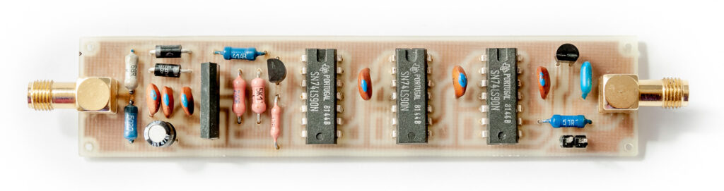
This version is built around a Telefunken U664BS divide-by-64 prescaler, which can often be found at hamfests or on eBay for around 2–10 euros (or 300–800 HUF in Hungary, from old stock).
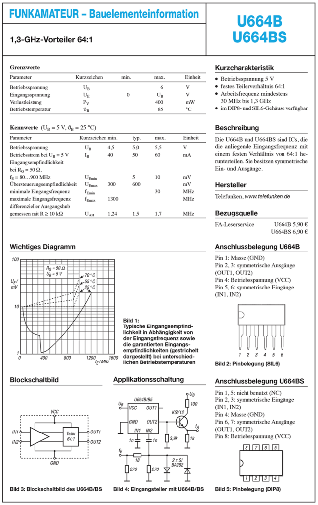
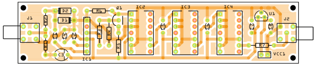
The U664BS front-end prescaler operates from 30 MHz up to 1.3 GHz. (If you have the older U664B variant, it’s limited to 1.0 GHz.) Its input sensitivity is around 5–10 mV (with Rg = 50 Ω). Since the maximum input signal level is 600 mV, a limiter circuit (D1–D2–R2) is included for protection.
The prescaler IC (IC1) first divides the input frequency by 64. After that, a chain of 74LS90 decade counters further divide the signal: each 74LS90 is configured to divide by 2.5. With three such stages, the total division factor becomes:
64 × 2.5 × 2.5 × 2.5 = 1000
So, if your frequency counter shows 1.000 MHz, the actual input frequency is 1000 MHz.
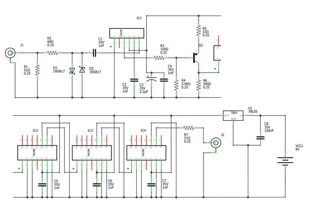
Since the U664BS is an ECL (Emitter-Coupled Logic) device, its output is not compatible with TTL or CMOS logic. It typically produces a signal around 0.8 Vpp with a DC offset. To interface with TTL-level inputs, a simple level shifter is used: a PNP transistor (Q1), such as a BF324 or BC556B, converts the signal to standard logic levels.
All integrated circuits are powered from a +5V supply provided by a 78L05 voltage regulator (U1). Note that the 78L05 is not protected against reverse polarity: if power is connected backward, it can conduct current internally and potentially destroy both the regulator and the entire circuit. – According to the LM7805 datasheet from Texas Instruments, a low-impedance path exists (via internal diode D1 and the base–collector junction of Q12) when the GND and VIN terminals are reversed.
To prevent this, a series diode (e.g., 1N4007) should be added before U1’s input.
Board Features
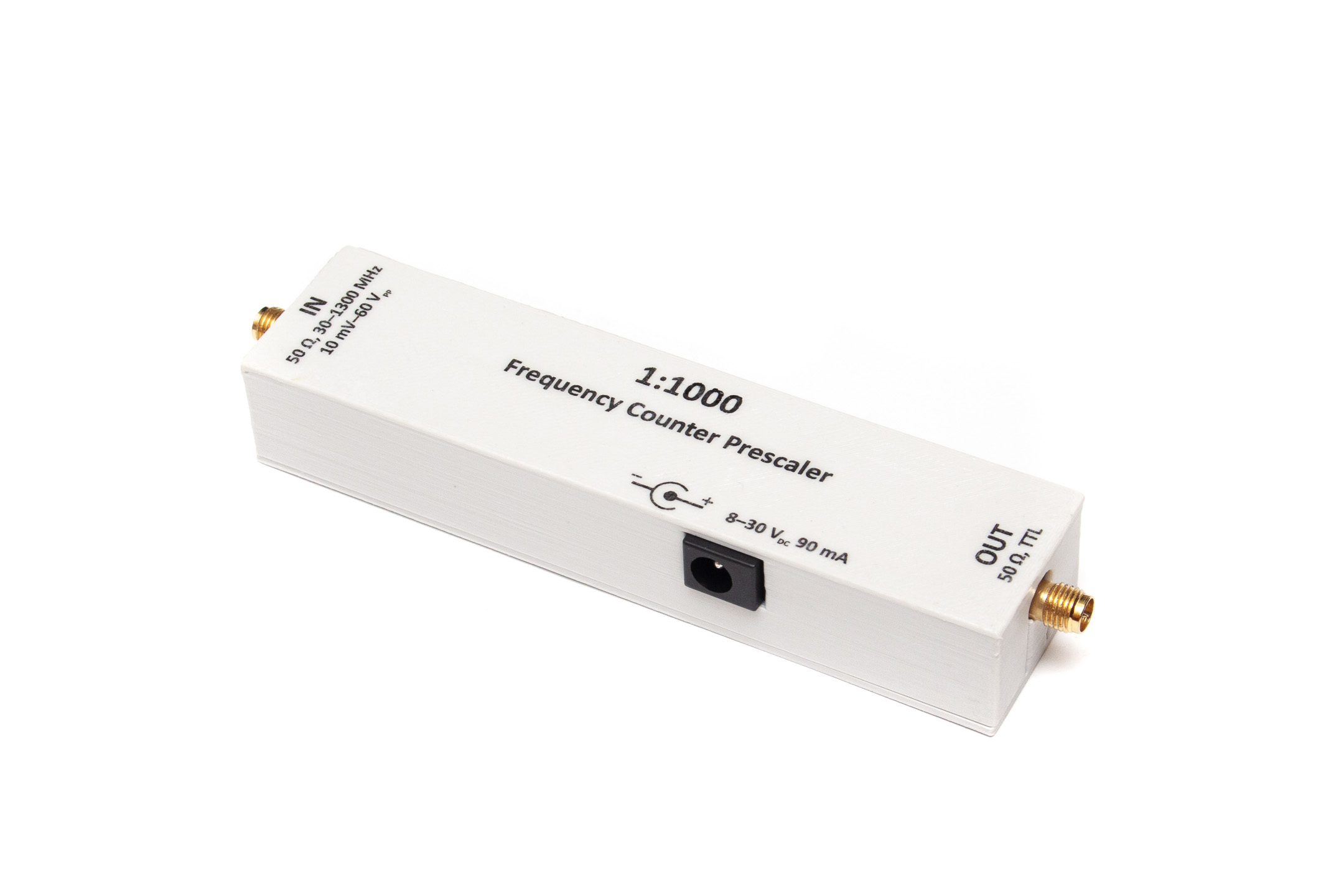
- Input frequency range: 30–1300 MHz
- Division ratio: 1:1000
- Input sensitivity (VHF/UHF): ≤10 mV
- Input impedance: 50 Ω
- Maximum safe input voltage: 60 Vpp (see note below)
- Supply voltage: 8–30 V
- Supply current: max. 90 mA
Note: The U664BS is only rated for a maximum of about 600 mV input. Exceeding this can damage the chip. The limiter circuit is essential for protection.
You can download the STL file for the 3D-printable box here: https://www.thingiverse.com/thing:6150412
Reverse Polarity Protection Mod
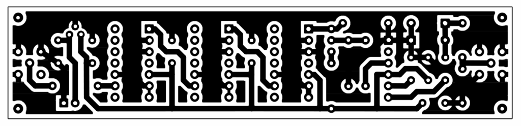
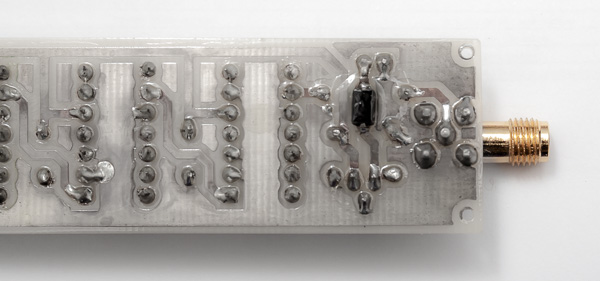
After writing this article, I decided to add a diode for reverse polarity protection. There was no space for it on the PCB, so I cut the power trace leading to the 78L05 regulator and soldered a small SMD diode in series directly on the copper track.
Datasheet of U664B / U664BS