
Nowadays, in the age of semiconductor diodes, many people don’t even know what this thing is. Yet, they were used in radio and television receivers up until around 1975. Recently, at a ham radio flea market, I picked up an AEG selenium rectifier for a few forints. I started searching online for its datasheet, but I have to admit, with little success. However, I did stumble upon the Selenium Rectifier Handbook, which, of course, doesn’t mention my specific selenium rectifier, but it does contain a lot of useful information about selenium in general.
A Brief History of Rectification
Converting alternating current to direct current was already a key issue back when Tesla and Edison fought their famous AC–DC battle (here’s a short film about it). One of the outcomes of this battle was the electric chair—along with Tesla’s victory and the triumph of alternating current. While AC was cheaper and easier to transmit, many electronic devices required DC, so rectification became an everyday necessity.
Before 1905, rectifiers were purely electromechanical devices. Two main types of electromechanical rectifiers became common: the vibrator type and the motor type.
The vibrator solution used an electromagnet to vibrate a reed, which operated switches that routed the current with the correct polarity. Essentially, it was like the reverse of the vibrator inverter used to convert DC into AC. This device could only handle small currents. Sometimes it was combined with a voltage regulator, and it could still be found in some motorcycles as late as the 1950s.
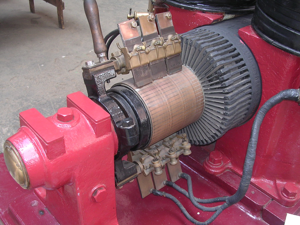
The motorized rectifier, on the other hand, could handle much larger currents—up to 10–20 kA. In this machine, a synchronous motor rotated a shaft at a rate synchronized to the AC frequency. On the shaft was a switching mechanism, the commutator. The commutator changed the connections in sync with the current, ensuring that the output current always flowed in the same direction. Of course, this didn’t produce a clean, smooth DC like a battery—it sparked, clattered, and produced a pulsating current. Their lifespan was limited to a few thousand operating hours. Dirty contacts and carbon brushes required constant maintenance. Despite these drawbacks, they were used in electric locomotives for a long time. Today, however, silicon diodes and thyristors have rendered them obsolete.

At the time, there were also electrolytic rectifiers. These consisted of two electrodes made from suitable materials (e.g., aluminum and lead) immersed in a salt solution (for example, a solution of tri-ammonium orthophosphate), much like a galvanic cell. The system conducted current more easily in one direction than in the other, making it suitable for rectification—though only for small currents and up to about 30 °C. Popular Mechanics Co.: The Boy Mechanic Vol. 1 featured such a DIY rectifier in 1913. Anyone who enjoys experimenting could play with one, but only at low voltages, because the device is quite dangerous and poses a significant risk of electric shock.
Few realize that electrolytic rectifiers haven’t completely disappeared even today—they are still in use, albeit in different applications and forms: they eventually evolved into the electrolytic capacitor.
Another important chapter in the history of rectification is the mercury-arc rectifier. This device was invented by Peter Cooper Hewitt in 1902. Essentially, it was similar to an ordinary cold-cathode mercury vapor lamp, except that the cathode here was not solid metal but liquid mercury, which could renew itself. Mercury cathodes emit electrons easily, whereas the carbon anode emits them with difficulty, so current in the tube flows in only one direction.
Multi-phase tubes were also made, with as many anodes as there were phases supplying them. These rectifiers were manufactured from the 1920s and remained in use until the 1970s, for example, to power traction motors in trolleybuses. To initiate an arc discharge in the mercury vapor, a high voltage was needed—this was usually accomplished by an auxiliary (starting) electrode. After ignition, the tube could operate at relatively low voltages (20–30 V) and handle substantial currents (100–500 A).
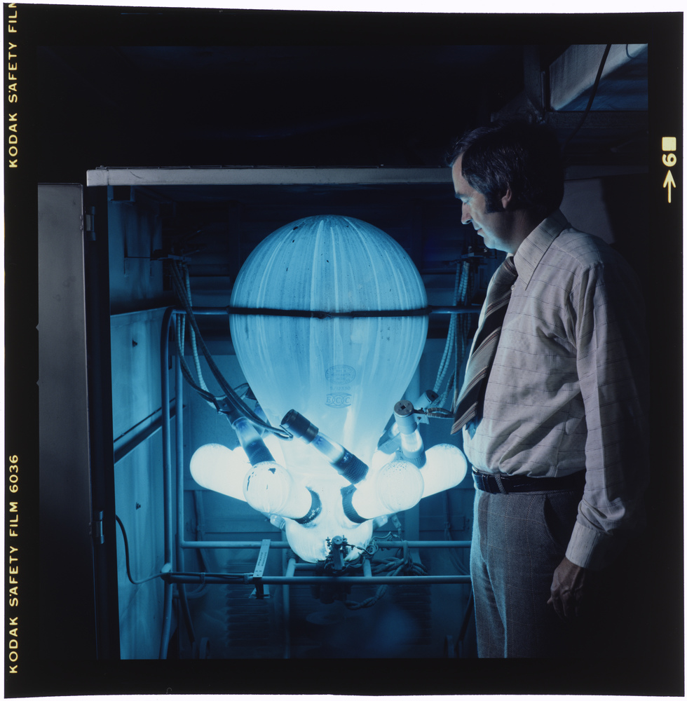
Smaller mercury-arc rectifiers were built with a glass envelope. The large, octopus-like glass body had arms that served as anodes, with the cathode at the bottom center, a starting electrode above it, and a central bulb—the “octopus body”—which allowed the mercury vapor to cool and condense, flowing back to the bottom. The fragility of glass was problematic for high-power rectifiers, as the pressure of the heated mercury vapor could become significant during operation.
For this reason, high-power models were made with steel tanks and porcelain feedthrough insulators. When the steel tank was water-cooled, the device could handle several thousand amperes. However, mercury leakage was a persistent problem in these steel-tank designs.
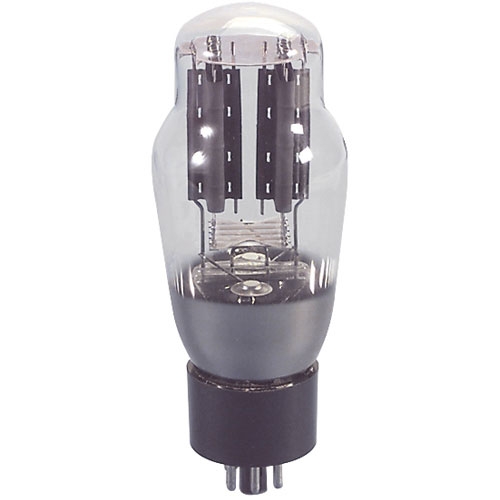
In 1904, John Ambrose Fleming patented the Fleming valve, or the rectifying vacuum diode. After that, vacuum diodes began to be widely manufactured and used. By 1914, high-power types capable of supplying X-ray tubes were already in production. In radios and other electronic devices, vacuum diodes remained in service until the 1970s, when they were finally displaced by semiconductor diodes [1].
However, there were devices where using a vacuum diode was not practical. Vacuum diodes could only rectify relatively small currents, while requiring a high operating voltage. For example, in a battery charger—where high currents are needed but the voltage is only a few volts—a vacuum diode was unsuitable.
My father once had a Pannónia motorcycle battery charger that consisted of just a transformer and a selenium rectifier. Thanks to the transformer’s unusually thin iron core and the unique characteristics of selenium, the charger was completely automatic: you simply connected the battery, and it would charge nicely for as long as needed (though only for lead-acid batteries).
(A description of a similarly primitive device can be found here—although that one uses semiconductor diodes and limits the charging current with incandescent bulbs.)
Selenium
Copper-oxide and selenium rectifiers were first experimented with in the 1880s, developed by several companies such as Braun, Schuster, and Siemens [2]. They proved to be practical rectifying devices, but were not manufactured routinely until the 1930s. Copper-oxide and selenium rectifiers are roughly the same size and appearance; copper-oxide can handle slightly higher currents but withstands lower voltages.
Selenium rectifiers have a distinctive look: they consist of a stack of parallel plates. During manufacturing, the selenium layer is vapor-deposited onto an aluminum plate of the desired size. A counter-electrode layer made of a low-melting-point tin-cadmium alloy is then applied over the selenium layer. The barrier layer forms at the interface between the selenium and the counter-electrode after appropriate electrical forming. The finished cell is coated with a protective paint to guard against environmental effects.
One cell can withstand about 20–25 V in reverse bias, while the forward voltage drop is about 1 V. The maximum operating temperature is 130 °C. The larger the plate area, the higher the current it can handle—typically up to about 50 mA per cm². The required performance is achieved by connecting multiple cells in series and/or parallel.
My selenium rectifier consists of 14 cells per unit, which means it can rectify up to 14 × 20 V = 280 V. Each cell measures about 2 × 2 cm ≈ 4 cm², which corresponds to a maximum current of roughly 200 mA. In other words, it would be just right for powering a small vacuum tube device (e.g., a small amplifier). In forward bias, the total voltage drop is 14 V, which at maximum load means about 2.8 W of dissipated power—so it will warm up a bit under normal operation. This 14 V voltage drop makes it unsuitable for low-voltage applications, but given the high number of cells, I assumed from the start that it wasn’t designed for low-voltage use. Selenium rectifiers for lower voltages, such as those used in battery chargers, typically have fewer plates and larger plates to handle higher currents.
Selenium cells do not last forever, but their lifetime is much longer than that of vacuum diodes—they can last 60,000 to 100,000 operating hours. Another advantage is that they work immediately when powered on, with no warm-up time like vacuum tubes require. Selenium also tolerates short-term shorts relatively well and even provides some current-limiting effect. However, they are slow and have large parasitic capacitance, so they can only be used at low frequencies.
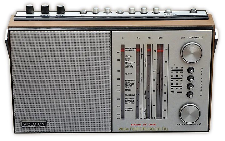
Interestingly, the Videoton RB 4602 Sirius de Luxe portable radio also used a selenium rectifier in its power supply, even though the device itself was fully transistorized and included semiconductor diodes. It hit store shelves in 1973 and represented a high level of technical sophistication for its time.
We had one at home, and it was excellent for receiving Radio Free Europe, so every Saturday morning it played in the kitchen—and we often took it along on fishing trips. It was the first Hungarian portable radio to feature a tuner with varicap diode tuning, allowing FM stations to be preset. The three programmed stations could be selected from the front panel using the small buttons on the right side. The fourth button only switched the AFC (Automatic Frequency Control) on and off—yes, it even had AFC!
The receiver could handle 3 AM bands (medium wave and two shortwave bands) and 2 FM bands (covering the full OIRT and CCIR FM ranges of the time). It contained 13 transistors and one integrated circuit (TDA220-01).
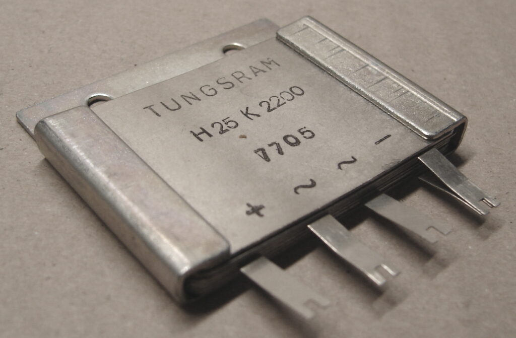
The standard RB 4602 Sirius operated on six 1.5 V D cells or with an external 9 V AC adapter; you can admire it on radiomuseum.hu. The “de Luxe” version, however, had a built-in AC power supply, which included a miniature Tungsram H25K500 selenium rectifier (its larger counterpart, the H25K2200 [25 V, 2.2 A], is still available from Árwill Elektronic BT for 295 Ft!).
It raises the question: why did engineers at the time design a selenium rectifier into a transistor radio?
To understand this, we need to consider the context of the era (1973). High-current silicon diodes and the bridge rectifiers built from them were not as widespread as they are today. For instance, the still-popular 1N4001…1N4007 series (1 A, 50 V…1000 V) was only introduced by Motorola Semiconductor in 1965 [3]. When the Sirius radio was designed, selenium was still very much a competitor to semiconductor diodes, and it was only natural to choose a Hungarian-made component rather than an American diode.
Selenium rectifiers had certain advantages in their time. Vacuum tube rectifiers were only about 60% efficient, meaning 40% of the power was wasted as heat. One reason was that vacuum diodes required heating, and another was that fast electrons striking the anode caused significant energy loss as heat. By contrast, selenium rectifiers had an efficiency of around 85%. They were robust, required no special handling, no heating, and no high-voltage supply.
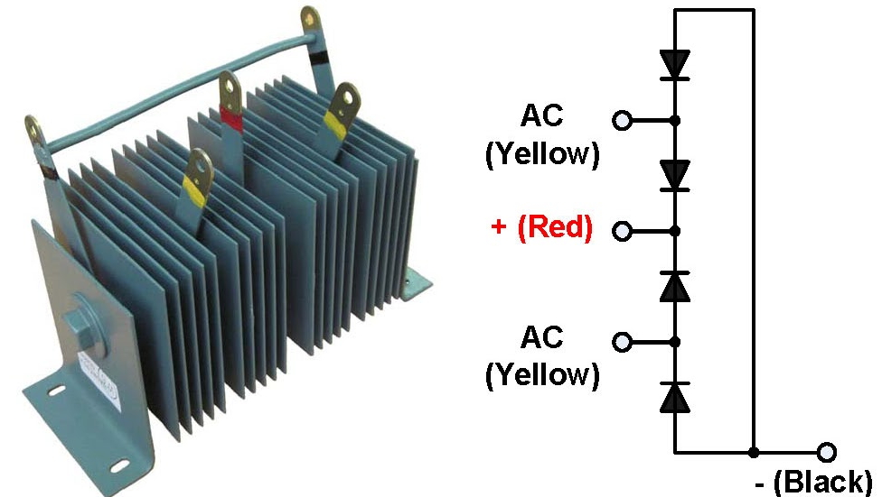
Building a bridge-type, full-wave rectifier (Graetz bridge) from selenium plates was straightforward, which also simplified and reduced the size of the mains transformer. For example, the vacuum tube rectifier shown earlier required two secondary windings, whereas a Graetz bridge only needed one.
A Bit of History of Science
The story would not be complete without mentioning that Hungary once produced high-quality selenium rectifiers. A key figure in this was Pál Selényi, an outstanding researcher in experimental physics. At the research laboratory of Egyesült Izzó (United Light Bulb Works), Selényi worked on the development of selenium-based light meters and photocells.
At the time, photocells were insensitive to red light, which was problematic for photography. Egyesült Izzó was the first to develop a sensor responsive to red light. During this work, Selényi not only studied the photoelectric behavior of selenium but also, as a by-product, improved selenium rectifiers to perfection.
He also conducted imaging experiments that demonstrated an invisible electrostatic charge image could be formed on a selenium cylinder and then made visible by powdering. However, the significance of this discovery went unrecognized at the time. Later, Chester F. Carlson—the inventor of xerography—acknowledged that Selényi’s publications formed the basis for his own work.
During World War II, Selényi’s career was derailed due to his origins: he was forced into early retirement and later sent to labor service. The illness he contracted there ultimately led to his death in 1954. Though he was elected a corresponding member of the Hungarian Academy of Sciences in 1948, the physics community showed little interest in his work. In 1950, he was awarded the title of Privatdozent and joined the Department of Experimental Physics at Eötvös Loránd University.
In Hungary, support and interest in Selényi’s research were minimal. Had political circumstances not interfered with his life, he might well have discovered the commercial potential of amorphous selenium-based photoconductive copying. The principle of electrostatic photocopying profoundly impacted human society. Without Selényi, the world might have had to wait another 10–20 years for xerography. The Xerox Corporation became one of the fastest-growing U.S. companies from 1950 onward.
After learning this, one must ask: is it worth doing anything as a physicist in this country, regardless of which way the political winds blow? [4]
References
- Valkó Iván Péter: Elektroncsövek és félvezetők. Tankönyvkiadó, Budapest, 1968. p. 766.
- H. P. Westman et al. (ed.): Reference Data for Radio Engineers, Fifth Edition, 1968, Howard W. Sams and Co., no ISBN, Library of Congress Card No. 43-14665, Chapter 13.
- Semiconductor Data Manual; Motorola; May 1965; archive.org
- Tar Domokos: Selényi Pál és a xerográfia. http://fizikaiszemle.hu/archivum/fsz9701/TAR-199701.pdf